
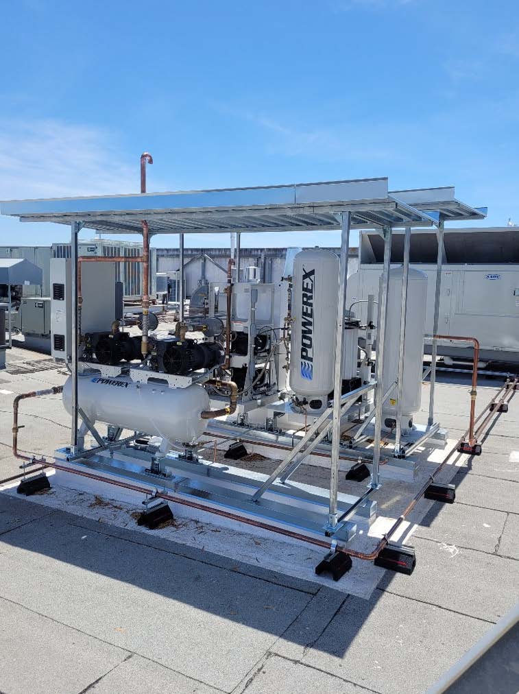
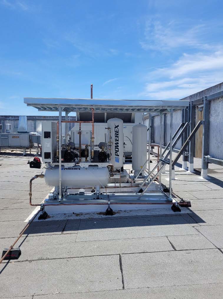
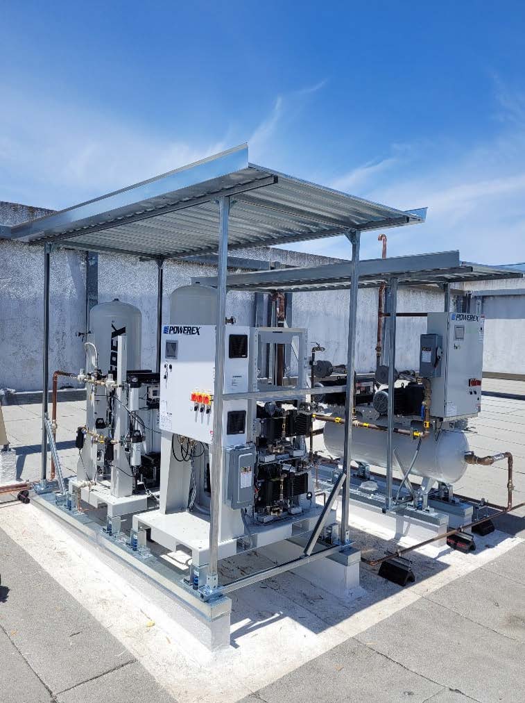
Installation of a Powerex Laboratory Lubricated Vane Vacuum System w/ Basic Controls and Powerex Laboratory Compressed Air System.
Installation of the following two systems:
AES-Powerex Laboratory Lubricated Vane Vacuum System with Basic Controls Specification
BASE MODEL NUMBER: AES-LVPD0303-AES-SPL-Tank Mount
SYSTEM CAPACITY: 34 SCFM @ 19” Hg
NOTE: 12 SCFM @ 21”HGVAC Each Vacuum Pump
HORSEPOWER: 6 HP Total (3HP x 2)
RECEIVER SIZE/CONFIGURATION: 80 Gal - Horizontal
ELECTRICAL: 460V, 3PH, 60Hz.
*NEMA 3R Control Panel with BACNET
*System performance shown with pumps running
Design Parameters: 7 SCFM @ 21”HGVAC (at Vacuum Pump)
General
The Powerex laboratory vacuum system is designed to create a suction system to remove unwanted fluids or gases from laboratory working areas. The laboratory vacuum system package is compliant with the NFPA 99 requirements for Risk Category 3 systems. Each system is completely tested before shipment and includes:
Each pump is factory piped to a common intake manifold. Vibration isolation pads are included with the system.
Rotary Vane Vacuum Pump
Each vacuum pump shall be rotary vane air-cooled design. Each vacuum pump shall be direct driven through a shaft coupling by a TEFC electric motor. Belt drives shall not be permitted. The vacuum pumps shall be mounted on vibration isolators.
Motor
The motor is continuous duty, C-face, TEFC, suitable for 208-230, or 460V, 3 phase, 60 hertz electrical operation.
Air Receiver
The system shall include an ASME rated air receiver. The tank shall be internally lined and come with a manual drain and sight gauge. Systems with Basic Controls are also equipped with a vacuum gauge. Receiver is plumbed so that system vacuum must pass through the air receiver prior to provide an additional protection for the pumps.
Premium NFPA Control Panel – Included
The control system provides automatic lead/lag sequencing and automatic alternation of all pumps in order to equalize the amount of usage among the available vacuum pumps. The Premium NFPA Control Panel shall include a gateway server card and all features listed below:
DISCHARGE TEMPERATURE SWITCH
The system is supplied with a high discharge air temperature shutdown alarm with visual and audible indicators and dry contacts.
SYSTEM CONNECTIONS
The system is supplied with a remote intake connection and flexible connectors for both intake and discharge. All piping complies with current NFPA 99 requirements.
OSHPD SEISMIC CERTIFIED
This system has been tested and certified in accordance with California’s Office of Statewide Health Planning and Development (POSHPD), California Building Code (CBC) 2013, and International Building Code (IBS) 2012.
NEMA 3R PANEL:
Optional Auto Purge –
Note: This option is available with our Premium NFPA Control Panel. It is not available on systems with Basic NFPA controls.
Systems with the auto purge feature will include:
Pumps will run through an automatic purge cycle ever 24 hours (after alternation phase), to purge any gases from the pump to atmosphere. A 3-position switch is provided to select automatic purge, manual purge, or purge off modes.
Note: Pneumatic purge isolation valves require 80 psi compressed air to be field supplied.
AES-Powerex Lab Compressed Air Model AES-LSQ05A4-AES-SPL Specification
BASE MODEL NUMBER: AES-LSQ05A4-AES-SPL x 2
SYSTEM CAPACITY: 50 SCFM @ 145 PSIG
HORSEPOWER: 20 HP Total (5HP x 4)
RECEIVER SIZE/CONFIGURATION: 120 Gallon - Vertical
ELECTRICAL: 208/230/460V, 3PH, 60Hz
(MUST SPECIFY VOLTAGE WHEN ORDERING.)
*NEMA 3R Control Panel
*System performance shown with all pumps running
General
The Powerex Laboratory Open Scroll Air Compressor System is designed to provide clean, dry air for applications where the quality of the compressed air is critical. The High-Pressure unit is rated for a maximum of 145 PSIG. Each system is completely tested before shipment and includes:
Open Scroll Air Compressor System
The package shall include multiple oil-less scroll air compressors and associated equipment. The only field connections required will be system intake, exhaust, and power connection at the control panel. All interconnecting piping, wiring, and vibration isolation pads are included with the system.
Oil-less Scroll Compressor Pump
Each compressor shall be belt driven oil-less rotary scroll single stage, air-cooled construction with absolutely no oil needed for operation. Direct drive compressors shall not be used.
Motor
Each compressor shall be belt driven by a 1750 RPM, TEFC, NEMA construction motor. Motors running at speeds higher than 1750 RPM shall not be acceptable. OSHA approved belt guards shall be provided.
Air Receiver
The system shall include an ASME air receiver rated for 200 PSI MAWP. The tank shall be equipped with:
Service Slide
The service slide enables easy maintenance access to each pump and motor base mount without having to remove them from the system.
Motor Slide Base
Maintenance feature designed for easy adjustment of belt tension from the motor slide on the base mount assembly.
Premium Control Panel
The control system provides automatic lead/lag sequencing and automatic alternation of all compressors to equalize the amount of usage among the available compressors. The Premium Control Panel shall include a gateway server card and all features listed below:
Dry contacts are provided on a labeled terminal strip for remote monitoring of all system alarms.
AIR PURIFICATION SYSTEM
MONITORING EQUIPMENT